It’s midway between an Arduino Mini (in measurement) and an Arduino Mega when it comes to computational capability, obtainable reminiscence and built-in peripherals.
For the reason that creation of the Arduino venture and the next unfold of the unique boards, the electronics trade and particularly the nascent electronics trade for Makers, has moved in two instructions: the creation and advertising and marketing of clone boards and the event of hybrid boards, designed so as to add to the market what the official Arduino household doesn’t provide.
Now we have not shirked this logic both, a lot in order that lately we’ve designed and proposed new Arduino prototyping boards which can be suitable and programmable with the official IDE, as within the case of the Fishino sequence boards.
Now we wish to return “to the cost” by proposing our newest discovery, which we’ve known as PRO midi 1284P, the place the phrase “midi” is said to the traits, which suggests one thing between a mini and a mega. The peculiarity of this new Arduino-like board is that it’s primarily based on the Atmel/Microchip ATmega1284P MCU. The board is proven in Fig. 1 and, as you may see, is extraordinarily small in measurement however stuffed with connections to the surface.
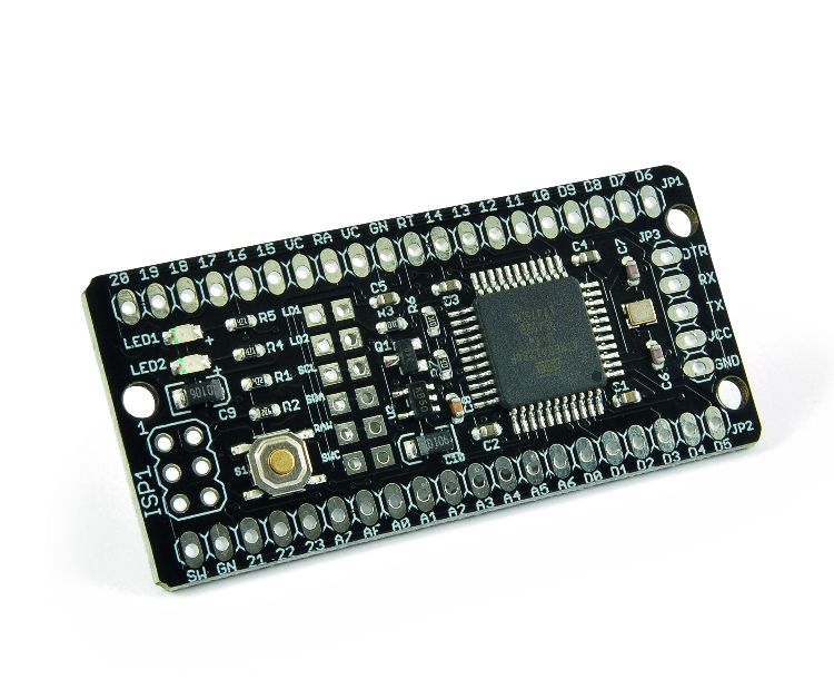
Fig. 1
The board presents, in a really small house, extraordinarily fascinating options:
- 16 MHz quartz-generated clock;
- 128 Kbytes of “FLASH” reminiscence (for code);
- 16 Kbytes of SRAM reminiscence (for knowledge);
- 4 Kbytes of EEPROM reminiscence (for knowledge, non-volatile sort);
- 3 {hardware} interrupts (INT0, INT1 and INT2);
- 2 serial ports;
- 1 I2C port;
- 1 SPI port;
- 32 GPIO pins of which 8 with PWM functionality;
- 8 analogue inputs with 10-bit ADC;
- 1 analogue comparator;
- 2 8 bits timers (Timer 0 and Timer 2); one among them (Timer 2) is usable as a “Actual-Time Counter” with exterior quartz at 32.768 kHz;
- 2 16-bit timers (Timer 1 and Timer 3);
- “Capacitive Contact Sense” utilizing the Atmel QTouch library.
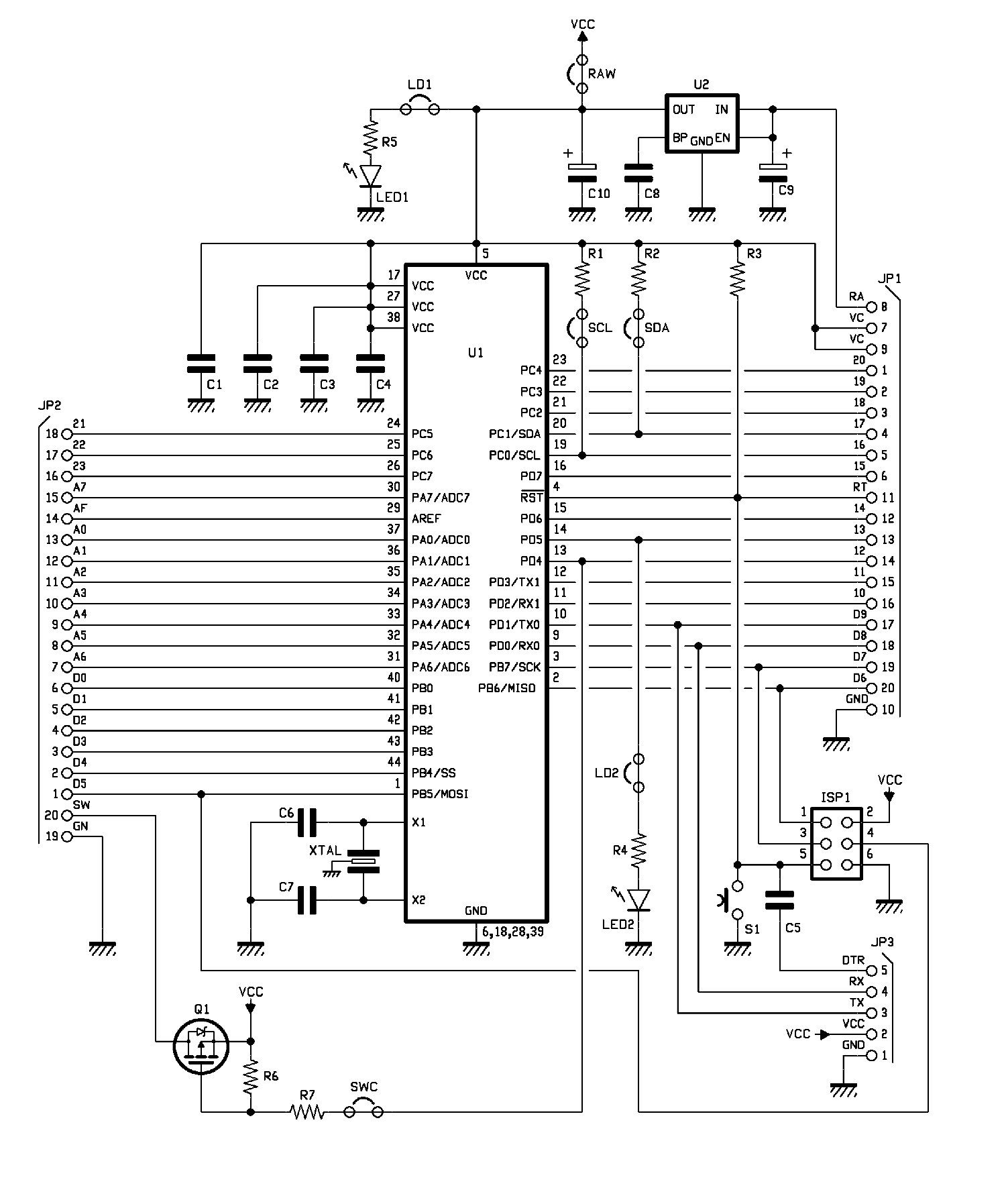
There are additionally (individually excludable by way of jumpers reduce and reset by the consumer) these peripherals (Fig. 2);
- Inexperienced LED (5V provide, will be excluded by reducing LD1 observe);
- Pink LED (D13 pin, will be excluded by reducing LD2 observe);
- MOSFET (pin D12, excludable by reducing SWC observe) to energy exterior objects (e.g. sensors), capable of activate/off masses as much as 700mA when utilizing an exterior 5V provide;
- 7 kΩ pull-up resistors on I²C bus traces (SCL and SDA will be bypassed by reducing their tracks).

Fig. 2
Between every pair of pitches, there’s a observe that may be interrupted by reducing it.
For these wishing to use an exterior energy provide apart from 5V (nonetheless as much as a most of 12V), the board is supplied with an LDO regulator (excludable by reducing the RAW observe) at 5V capable of energy (given the decreased dissipate energy) the one MCU, however not exterior customers.
Mainly, within the MCU, is loaded the “Optiboot” bootloader that, by way of a serial <-> USB adapter to be related externally (the board is supplied with a 5 pin connector to attach generic “serial <-> USB” adapters) permits simple programming by way of the Arduino IDE.
There may be nonetheless an ordinary ISP connector that permits programming the MCU by way of an exterior programmer, such because the Atmel ICE or every other AVR/ISP suitable programmer.
The size of the board are extraordinarily small, just like these of the “Arduino™ MKR” sequence, i.e. 56.1 mm x 26.3 mm and likewise the pinout is partially suitable with some boards of the identical MKR sequence.
The pins marked “TCK (18), TMS (19), TDO (20) and TDI (21)” will be related to a JTAG programmer/debugger for programming and debugging purposes.
On pins TOSC1 (22) and TOSC2 (23) will be related quartz at 32.768 KHz that, by correctly programming the Timer 2 (TC2), can present the clock to the “Actual-Time Counter” that mentioned Timer 2 is ready to implement, “Counter” that is ready to proceed to function even with the MCU in “Energy-Save” mode.
Due to the chance to exclude all {hardware} that isn’t wanted (LEDs, resistors, MOSFETs, LDO voltage regulator) by way of the suitable jumpers, the board is completely fitted to low-power purposes; actually, excluding all of the {hardware} that isn’t needed, the MCU, put in “Energy-Save” mode (if desired with the “Actual-Time Counter” at 32 kHz lively) absorbs solely 0.6 µA.
Regardless of its small measurement, the ATmega1284P microcontroller has half the Flash of an ATmega2560 (the MCU that equips the Arduino MEGA board) however has twice the SRAM (16 Kbytes) which makes this MCU very best for many who wish to develop purposes that use the real-time working system FreeRTOS; in such purposes, along with the big reminiscence for the code that the ATmega1284P offers, 128Kbytes, it’s important to have a big SRAM, since every activity that’s created, nonetheless wants its personal house for the stack and for its system variables.
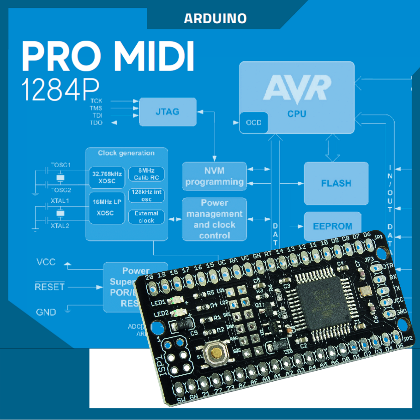
BLOCK DIAGRAM OF THE ATMEGA1284P
As already uncovered in earlier paragraphs, the core of the board Professional Midi 1284P is the microcontroller Atmel / Microchip ATmega1284P, perceive the traits of which is extra quick by casting a look at Fig. 3 which exhibits the block diagram “useful”. In it we see peripherals, modules and registers, along with the actual clock generator.
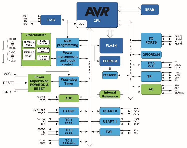
Fig. 3
Programming the ATMEGA1284P with Arduino IDE
As already talked about, the board will be programmed within the Arduino IDE setting.
To do that, the suitable “core” should be added to the IDE.
Open the IDE “preferences” and add the next line within the subject “Extra Boards supervisor URLs”:
https://mcudude.github.io/MightyCore/package_MCUdude_MightyCore_index.json
After that, you need to go to the Instruments menu, give the command Card Supervisor and choose, from the submenu that opens, as the cardboard the:
MightyCore
>Atmega1284
As soon as the tab has been chosen, it’s needed to pick out from the choices that seem:
Clock: “Exterior 16 MHz”
BOD: “disabled” (o il livello di tensione da voi scelto)
Compiler LTO: “LTO disabled”
Variant: “1284P”
Pinout: “Normal pinout”
Bootloader: “YES (UART0)”
On this means you’ve configured the IDE to make use of the board and, upon getting chosen the right serial port (the one created by the USB <-> serial adapter), it is possible for you to to load the code straight by way of bootloader.
To facilitate the writing of the code, a “.h” module is supplied that may be included within the venture and that defines, in a mnemonic means, a sequence of “pins” current on the “PRO midi 1284P” board. The title of this module is “ProMidi1284P.h” and will be downloaded from the obtain space of the journal and incorporates the definitions summarized in Itemizing 1.
Itemizing 1.
/*
Pins definitions addendum for ProMidi 1284P
Guglielmo Braguglia - Could 2019
*/
#ifndef Pins_ProMidi1284_h
#outline Pins_ProMidi1284_h
#ifdef LED_BUILTIN
#undef LED_BUILTIN
#endif
#outline LED_BUILTIN 13
#ifndef SWC_BUILTIN
#outline SWC_BUILTIN 12
#endif
#ifndef NOT_AN_INTERRUPT
#outline NOT_AN_INTERRUPT -1
#outline digitalPinToInterrupt(p) ( (p) == 10 ? 0 : (
(p) == 11 ? 1 : ( (p) == 2 ? 2 : NOT_AN_INTERRUPT ) ) )
#endif
#outline PIN_D0 (0)
#outline PIN_D1 (1)
#outline PIN_D2 (2)
#outline PIN_D3 (3)
#outline PIN_D4 (4)
#outline PIN_D5 (5)
#outline PIN_D6 (6)
#outline PIN_D7 (7)
#outline PIN_D8 (8)
#outline PIN_D9 (9)
#outline PIN_D10 (10)
#outline PIN_D11 (11)
#outline PIN_D12 (12)
#outline PIN_D13 (13)
#outline PIN_D14 (14)
#outline PIN_D15 (15)
#outline PIN_D16 (16)
#outline PIN_D17 (17)
#outline PIN_D18 (18)
#outline PIN_D19 (19)
#outline PIN_D20 (20)
#outline PIN_INT0 (10)
#outline PIN_INT1 (11)
#outline PIN_INT2 (2)
static const uint8_t D0 = PIN_D0;
static const uint8_t D1 = PIN_D1;
static const uint8_t D2 = PIN_D2;
static const uint8_t D3 = PIN_D3;
static const uint8_t D4 = PIN_D4;
static const uint8_t D5 = PIN_D5;
static const uint8_t D6 = PIN_D6;
static const uint8_t D7 = PIN_D7;
static const uint8_t D8 = PIN_D8;
static const uint8_t D9 = PIN_D9;
static const uint8_t D10 = PIN_D10;
static const uint8_t D11 = PIN_D11;
static const uint8_t D12 = PIN_D12;
static const uint8_t D13 = PIN_D13;
static const uint8_t D14 = PIN_D14;
static const uint8_t D15 = PIN_D15;
static const uint8_t D16 = PIN_D16;
static const uint8_t D17 = PIN_D17;
static const uint8_t D18 = PIN_D18;
static const uint8_t D19 = PIN_D19;
static const uint8_t D20 = PIN_D20;
static const uint8_t PIN_RX0 = PIN_D8;
static const uint8_t PIN_TX0 = PIN_D9;
static const uint8_t PIN_RX1 = PIN_D10;
static const uint8_t PIN_TX1 = PIN_D11;
static const uint8_t PIN_SCL = PIN_D16;
static const uint8_t PIN_SDA = PIN_D17;
static const uint8_t PIN_SCK = PIN_D7;
static const uint8_t PIN_MISO = PIN_D6;
static const uint8_t PIN_MOSI = PIN_D5;
static const uint8_t PIN_SS = PIN_D4;
#endif
For individuals who choose different improvement environments, we level out that the board is absolutely programmable utilizing the Microchip IDE MPLAB X each with the XC8 compiler (which at present solely helps ‘C’ code) and by putting in the particular “AVR Toolchain” (which additionally permits loading ‘C++’ code). The benefit of utilizing such an setting is that, by connecting the board to a JTAG programmer/debugger supported by MPLAB X, it’s not solely doable to program the MCU, however additionally it is doable to do actual debugging each by inserting breakpoints and by executing the code in step-by-step mode.
Utilizing “ISP” programming, or “JTAG” programming, with the assistance of an exterior programmer, the “bootloader” is cleared. If you wish to restore the board to the unique situations, with the “bootloader” and the “blink” program preloaded, merely obtain from the obtain space of the journal the file named “ProMidi.hex” and, once more with the assistance of the exterior programmer, load this file on the board.
If the values of the “FUSE” have additionally been altered, they are often restored to the next unique values utilizing an exterior programmer:
Low = 0xD7, Excessive = 0xDE, Ext = 0xFD.
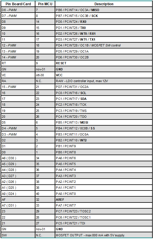
Relating to pinouts, Desk 1 offers detailed details about every pin that the Professional Midi 1284P board offers.
Desk 1
MOSFET ON/OFF CIRCUIT DIAGRAM
As talked about, the Professional Midi 1284P is supplied with a change, primarily based on a MOSFET FDN360P, that is ready to activate and off masses related between the SW pin of the board and the GND pin. This transistor permits to manage of masses with most absorption of 800mA and solely within the presence of an exterior stabilized energy provide able to offering the mandatory present (so when the board is powered by way of the RAW pin). It’s managed by pin D12 (Fig. 4).
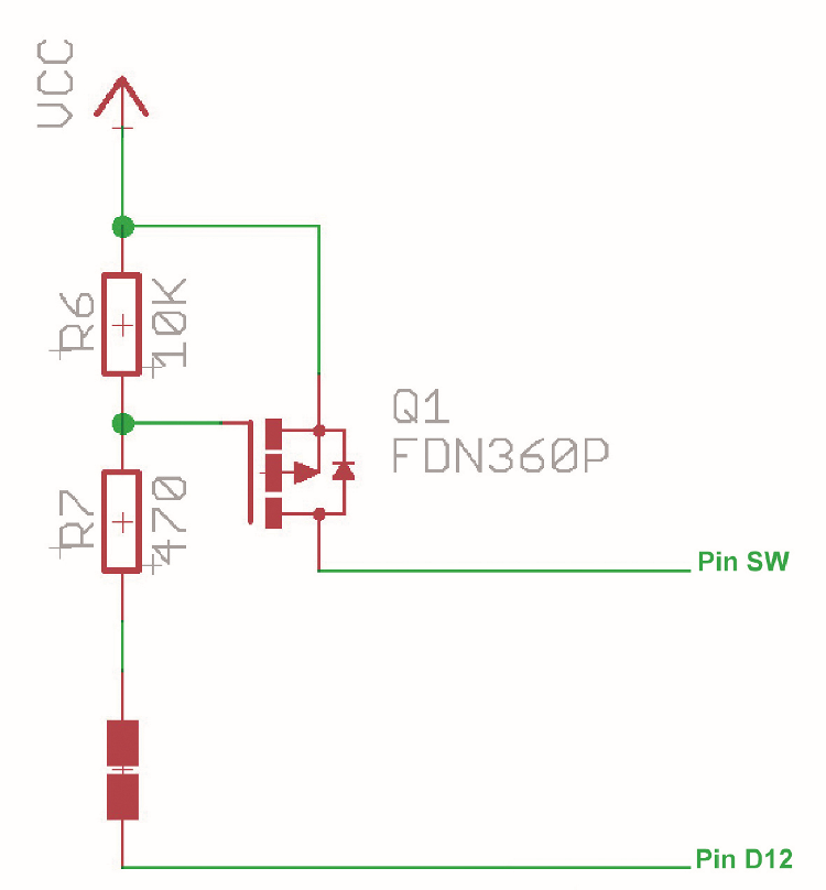
Fig. 4
BOM:
R1, R2: 4.7 Kohm (0603)
R3, R6:10 Kohm (0603)
R4, R5, R7: 470 ohms (0603)
C1, C2, C3, C4, C5: 100 nF ceramic (0603)
C6, C7: 18pF ceramic (0603)
C8: 470 pF ceramic (0603)
C9: 10 µF 10V tantalum
XTAL: Quartz 16 MHz
U1: ATMEGA1284P-AU
U2: MIC5205-3.3YM5-TR
LED1: Inexperienced LED (0805)
LED2: Pink LED (0805)
Q1: FDN360P
S1: Microswitch
Numerous
– 5-way male strip
– 20-way male strip (2 pcs.)
– 2×3-way male strip
– Printed circuit S1493 (57×27 mm)
CONCLUSIONS
The Professional Midi 1284P that we’ve introduced on this article is the best board for many who, whereas wanting to stay within the Atmel AVR household, wants a considerable amount of each Flash reminiscence for its code and SRAM reminiscence. Exactly the big quantity of the latter (it’s effectively 16 kB), makes it the best board for many who wish to develop purposes with the assistance of the working system “real-time” FreeRTOS ™, whereas sustaining the simplicity of programming in an Arduino setting due to the aforementioned “MightyCore“, installable from the IDE add-in card supervisor.
The extraordinarily small measurement permits then the insertion in extraordinarily compact gear and, due to the potential for eliminating the “superfluous” (LEDs, pull-up, and so forth..), even at very low energy consumption (it’s a few microamps).
FROM OPENSTORE