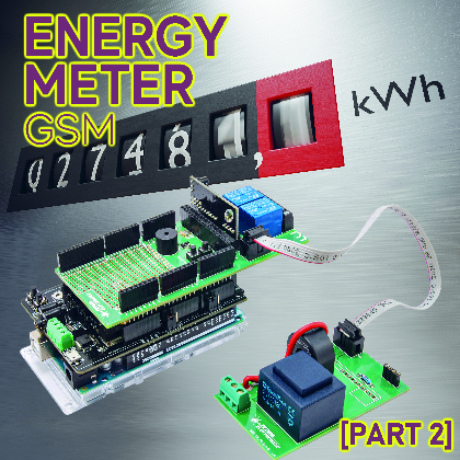

It screens the electrical energy consumption and sends the detected information to the cloud by the GSM mobile community; it’s primarily based on an Arduino Mega geared up with GSM Defend and a board on which the measurement board is mounted. Second and remaining instalment.
Within the earlier put up on Open Electronics, now we have proposed the conclusion of a challenge created to watch electrical energy consumption by a board for detection of voltage and present within the plant, completely managed by an Arduino Mega 2560 board geared up with a GSM Defend, which implements the information connection on cellular radio community aimed toward sending to a distant server of the detected information.
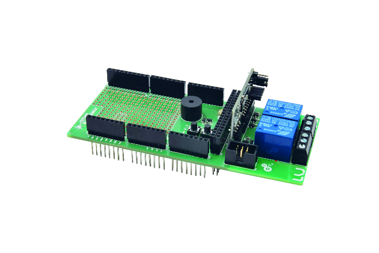
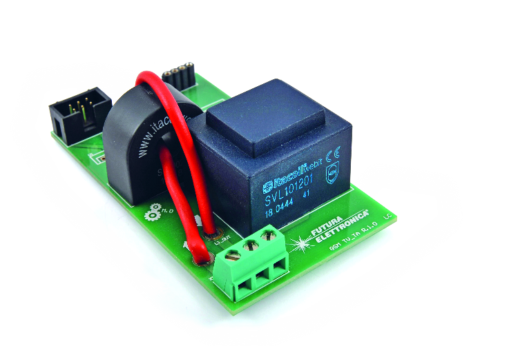
Bodily, the challenge consists of a sensor board that mounts the traditional present transformers (TA) and voltage transformers (TV) on, which might happen in a specific feminine strip; the module Power Meter FT1346M is provided with a 2.54 mm pin pitch, in addition to a defend made to be utilized to Arduino Mega 2560 or Fishino Mega board; as well as, there’s a GSM Defend for cellular information connectivity.
The challenge gives two prospects of use: the configuration simply described is the one for the appliance proposed on this article, i.e., the {hardware} managed by Arduino/Fishino Mega, and gives that the board with TA and TV transformers is a straightforward sensor of the parameters of {the electrical} energy and is interfaced by the suitable connector and its flat-cable to the GSM Power Meter defend. This configuration permits the Arduino/Fishino Mega to accumulate and course of absorption information and the eventual sending through GSM/GPRS community.
However it’s also attainable to make use of the TA-TV board alone together with a Private Laptop. Nonetheless, the FT1346M module have to be plugged into its feminine strip and never into the Power Meter defend as within the full configuration with Arduino.
The guts of the measurement is the FT1346M module, which wants the board with the TA and TV transformers. Nonetheless, it detects the corresponding voltages and determines section, energy issue, instantaneous absorption, obvious energy, energetic and reactive, just by analyzing the connection between the waveforms offered by the 2 transformers. It’s then the FT1346M that communicates the information to the pc by the interface connector.
The FT1346M is predicated on the MCP39F511 built-in circuit, which makes use of a sampling algorithm that takes a finite variety of samples per cycle of the mains AC. The buildup interval of the samples is given by the integer worth 2N, which identifies the variety of line cycles on which you wish to pattern and consequently carry out calculations. For instance, with N mounted at 5, you’ve got that the road cycles on which you’ll carry out sampling and computation shall be 32.
Effectively, after this abstract of the challenge and a brush up on the operation of the built-in circuit that measures the ability parameters, let’s choose up the dialog from the place we left off within the first episode (through which we defined the {hardware} and the library for Arduino) that’s the sketch that has been ready to make use of the challenge in its full model, that’s with the Power Meter defend.
Sketch Test_MCP39F511
The sketch, written to work on the Arduino Mega 2560 or Fishino Mega boards, is proposed as a primary method to utilizing the brand new MCP39F511 administration library. That is divided into six separate recordsdata that we’ll touch upon under:
- “Test_MCP39F511“. ® The principle file containing variable declarations used within the sketch, string constants, and the 2 normal capabilities of Arduino initiatives: void Setup() and void Loop();
- “DigitalInput® Administration file of the enter I/O, that’s the two buttons P1 and P2 current on the demo board GSM EnergyMeter R.1.1;
- “DigitalOutput® Administration file of the output I/O or the 2 relays K1 and K2, the buzzer and the service LEDs LD1 ÷ LD4 all the time current on the demo board GSM EnergyMeter R.1.1;
- “Measures® Administration file for studying electrical measures and visualization on serial monitor, if enabled;
- “TimersInt® File of administration of the interrupt of system TIMER 5 containing the code of management of the temporal variables used within the sketch. TIMER 5 acts as a time base with 2 ms decision;
- “Uart_to_Uart“. ® Administration file for the serial communication between the Arduino Mega 2560 board and the EnergyMeter software program put in on the PC. In observe, the information packets despatched by the software program, since it’s not instantly linked to the built-in into {hardware} mode, are intercepted and despatched to the MCP39F511 built-in. Because of this, responses from the built-in are intercepted and despatched to the PC software program.
Let’s analyze the principle file “Test_MCP39F511,” the place on the prime we discover a collection of constants declarations, together with the I/O to that are linked each buttons and relays, in addition to LEDs and buzzer. These I/O are solely out there on the Arduino Mega 2560 boards. That is adopted by a collection of constants for managing the state machines used within the sketch and output I/O administration.
We’ve then outlined a relentless threshold past which the system goes into alarm (500 W, modifiable by urgent the button P1, which we’ll focus on later) and an offset fixed that, mixed with the earlier one, places the system in pre-alarm.
That is adopted by string constants for use for printing on the serial monitor some data and {the electrical} measurements taken. Lastly, now we have the declarations of the state machines used and the variables wanted for the sketch to work.
To raised perceive the firmware, we can assist ourselves with the flowchart proven in Fig. 1, which highlights each the “void setup()” part of the sketch and the “void loop()” operate of the sketch.

Fig. 1
The setup operate used to configure the sketch consists of the configuration of the TIMER 5 used to handle time variables, the configuration of enter I/O (buttons), the configuration of output I/O (relays and buzzer), and the configuration of the UART of the serial monitor and the connection to the MCP39F511. The library interrupts are then enabled, the library I/O pins are configured, and at last, the reset situation of the MCP39F511 is launched. Final however not least, the state machines used within the sketch are configured, some variables are configured, and the revision variety of the sketch in use is printed on the serial monitor.
As soon as initialization is full, the system enters the “void loop()” operate the place the next capabilities are executed (see the second part of the flow-chart):
- debouncing the 2 buttons P1 and P2;
- state machine administration for the capabilities related to the 2 buttons P1 and P2;
- state machine administration for studying electrical measurements;
- state machine administration for Uart-To-Uart operate; this operate requires working the software program on EnergyMeter PC R.1.0.4.0 or larger;
Suppose the intervention thresholds usually are not being set utilizing button P1. In that case, the operate of monitoring the energetic energy engaged regarding a preset intervention threshold is carried out to warn utilizing an acoustic-visual sign when the ability threshold is exceeded. The system solely warns of the overrun and doesn’t act on the 2 relays on the board, which could be energized or de-energized by urgent the buttons P1 and P2. If a threshold configuration is in progress by urgent button P1, this operate is ignored till initialization is full.
If the EnergyMeter software program is working, it may benefit from the UART of the Arduino IDE’s serial monitor to speak with the MCP39F511 IC. In different phrases, the UART of the serial monitor acts as a bridge between the software program and the built-in. On this means, you possibly can configure the registers of the built-in unit or learn {the electrical} measurements instantly and show them on the PC monitor. This performance has been named Uart-To-Uart. If it’s not energetic, the flowchart continues with the next out there capabilities. In any other case, it returns to the pinnacle, repeating the above capabilities.
The system, each two seconds, begins a session of studying the registers containing {the electrical} measurements. In different phrases, it prompts the learn state machine seen within the earlier factors.
In case you are not working a readout session, {the electrical} measurements are printed on-screen on the serial monitor each ten seconds.
The P2 button can activate the Microchip manufacturing facility parameter reset operate. To do that, press the P2 button for not less than 6 seconds after which launch it. The yellow LED LD2 will point out this choice. On this case, the system will ship a textual content string with a particular code to the MCP39F511 in order that it may begin its inner process to reset the parameters. If you wish to reset the FT1346M to manufacturing facility settings, press P2 for greater than 3 seconds however lower than 4 seconds. The crimson LED LD1 will point out this choice. On this case, the EEPROM of the MCP39F511 is learn to retrieve the restoration information and ship them to the built-in circuit.
BUTTONS MANAGEMENT
This concludes the outline of the principle loop. Let’s then contemplate the administration of the P1 and P2 buttons.
If pressed for a interval of lower than 1 second, pushbutton P1 energizes/de-energizes the corresponding relay K1; the identical applies to pushbutton P2, nevertheless it refers to relay K2.
Button P1 is related to the operate of setting the intervention threshold. The default worth loaded at power-up is all the time 500 W, with an offset of 100 W.
Which means that if 500 watts are exceeded, the system goes into alarm (crimson LED LD1 ON; the buzzer emits an acoustic sign to warn that the brink has been exceeded), but when it stays under 400 W, the system is in regular circumstances (inexperienced LED LD3 on). Between 400 W and 500 W is pre-alarm (yellow LED LD2 lit).
Altering the brink worth adjustments the set off level, whereas the offset stays unchanged.
So the thresholds that may be set by button P1 are as described under.
- Extended stress for not less than 1 second. LED LD1 comes on to point the choice of 1 kW. For those who launch button P1, the buzzer emits one beep to verify the choice.
- Press and maintain for not less than 2 seconds. LED LD2 illuminates to point the choice of 2 kW. For those who launch button P1, the buzzer emits two beeps to verify the choice.
- Press and maintain for not less than 3 seconds. LED LD3 illuminates to point the choice of 3kW. For those who launch button P1, the buzzer emits three beeps to verify that the brink has been chosen.
- Press and maintain for not less than 4 seconds. LD1 and LD2 LEDs illuminate to point the choice of 4 kW. For those who launch button P1, the buzzer emits 4 beeps to verify the choice.
- Press and maintain for not less than 5 seconds. LEDs LD1 and LD3 gentle as much as point out the choice of 5 kW; if you happen to launch button P1, the buzzer emits 5 beeps to verify the choice.
- Extended stress for not less than 6 seconds. LD2 and LD3 LEDs illuminate to point the choice of 6 kW. For those who launch button P1, the buzzer emits six beeps to verify the choice.
Now let’s transfer on to the P2 button; that is used to energise/de-energize relay K2 if pressed for lower than one second. In any other case, it’s used to revive the manufacturing facility parameters. Specifically, if the P2 button is pressed for not less than 3 seconds, the manufacturing facility parameters of the FT1346M measurement board are restored.
The LD1 LED lights as much as point out the FT1346M manufacturing facility parameter reset choice. When the button is launched, the process is began. As well as, a string is printed on the serial monitor to point what has been finished.
Then again, if the P2 button is pressed for not less than 6 seconds, the Microchip manufacturing facility parameters are restored by sending the suitable serial command. The LD2 led lights as much as point out this choice; when the button is launched, the process is began, and the string denoting the profitable restoration operation is printed on the serial monitor.
As for {the electrical} measurements dealt with by the sketch, now we have the next:
- RMS voltage (library operate referred to as cmd.MCP39F511_ReadRmsVoltageRaw();)
- Present RMS (library operate referred to as cmd.MCP39F511_ReadRmsCurrentRaw();)
- Community frequency (library operate referred to as cmd.MCP39F511_ReadLineFrequencyRaw();)
- Energy issue (library operate referred to as cmd.MCP39F511_ReadPowerFactorRaw();)
- Obvious energy (library operate referred to as cmd.MCP39F511_ReadApparentPowerRaw();)
- Lively energy (library operate referred to as cmd.MCP39F511_ReadActivePowerRaw();)
- Reactive energy (library operate referred to as cmd.MCP39F511_ReadReactivePowerRaw();)
As for the ability issue, you should additionally name the Cmd.CalcPowerFactor() operate calculates the right worth for the reason that information learn is in two’s complement. When {the electrical} measurement is printed on the serial monitor, it’s adjusted in response to the decimal locations assigned to the varied measurements. For instance, for RMS voltage measurement, now we have:
Serial.println((float)(Cmd.VoltageRmsRaw.uWord/(pow(10, VOLTAGE_DEC))));
Then the learn worth of the RMS voltage, saved within the acceptable library information construction, is split by an influence of 10 and so forth for all different measurements.
Let’s make one final consideration: on the prime of the file “Test_MCP39F511“, there’s a directive to the compiler named “ONLY_SOFTWARE_ENERGY_METER.” That is normally commented out and subsequently disabled. If you take away the remark and recompile the sketch, you’ll have that the one energetic operate within the “void loop()” would be the “Uart-to-Uart” operate for the configuration of the measurement board utilizing EnergyMeter software program R.1.0.4.0 or larger.
PC SOFTWARE
EnergyMeter R.1.0.4.0:
Let’s conclude with some transient feedback on the brand new model of the software program EnergyMeter R.1.0.4.0, which gives a collection of instructions for managing the EEPROM reminiscence of MCP39F511.
Fig. 2 exhibits the brand new interface of the software program, the place now we have highlighted in crimson the brand new instructions created that we’re going to describe:
- Write Calibration Registers and Freeze FT1346 Eeprom Manufacturing unit Information“. this command sends the information to the calibration registers of the MCP39F511 and, on the similar time, saves the information in EEPROM within the acceptable reminiscence areas;
- Write Design Configuration Registers And Freeze FT1346 Eeprom Manufacturing unit Information“. this command sends the information to the configuration registers of MCP39F511 and, on the similar time, saves the information in EEPROM within the correct reminiscence areas;
- View MCP39F511 Eeprom” . with this command, the administration window of the EEPROM reminiscence of the MCP39F511 is named.
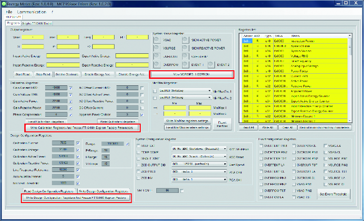
Fig. 2
Fig. 3 highlights the EEPROM reminiscence administration window; the desk exhibits the information ultimately saved within the reminiscence. As already broadly stated, that is divided into pages. Every web page consists of 8 Phrase for a complete of 16 bytes.
On the left facet of the consumer interface, we discover the instructions to learn or write information from a file on the pc; that is helpful when it’s important to take information from an EEPROM after which write them into the reminiscence of one other FT1346M measuring board, or when it’s important to program a collection of measuring boards.
So, to summarize:
- “Save MCP39F511 Eeprom Information File“. saves in a file the information ultimately learn from the EEPROM reminiscence;
- “Learn MCP39F511 Eeprom Information File“. reads information from a beforehand saved file;
- “Reset Desk Values® resets the information displayed within the desk again to the default values or 0xFFFF.
On the fitting of the consumer interface display, as an alternative, we discover the instructions to learn, write or erase the EEPROM reminiscence of the MCP39F511 built-in circuit mounted on the FT1346M measurement board. Particularly, now we have:
- “Reads All Eeprom Pages from the MCP39F511“. reads all EEPROM reminiscence pages from the MCP39F511 and shows their content material within the desk;
- “Writes All Eeprom Pages of the MCP39F511“. writes all of the EEPROM reminiscence pages of the MCP39F511, taking their values from the desk;
- “MCP39F511 Bulk Erase EEPROM“. executes the overall erasing of the EEPROM reminiscence bringing it again to the default worth that’s 0xFFFF;
- “Reads a single EEPROM web page from the MCP39F511“. Reads a single web page of EEPROM reminiscence and exhibits its content material within the desk. On the left is the textual content field through which to enter the reminiscence web page you wish to learn;
- “Writes a single EEPROM web page of the MCP39F511“. Writes a single EEPROM reminiscence web page of the MCP39F511; information are taken from the corresponding reminiscence web page proven within the desk.

Fig. 3
Final however not least, now we have the configuration window of the settable thresholds of the MCP39F511 built-in circuit. 4 exhibits the brand new window with the most recent out there command (within the software program launch we’re describing) highlighted in crimson, which permits us to put in writing the brink values within the acceptable registers and to save lots of them within the EEPROM reminiscence.

Fig. 4
CONCLUSIONS
With this, we will say that now we have concluded the dialogue of the Arduino library for managing the MCP39F511 built-in circuit in all its kinds and an intensive method. Due to this piece, we will now transfer on to integrating the identical in a knowledge administration system with our GSM board or some other digital board for interfacing to a database for the administration and show {of electrical} measurements acquired. We shall be growing an utility of the system with different {hardware} sooner or later, so comply with alongside.
FROM OPENSTORE
VOLTAGE MEASUREMENT TRANSFORMER
CURRENT MEASUREMENT TRANSFORMER