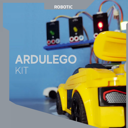
A lot of parts to make functions that may be programmed with Arduino and assembled like LEGO bricks.
What number of instances did you dream of constructing one thing with LEGO bricks while you had been a toddler and see it transferring, animated, maybe integrating a specific amount of programmable electronics to maintain up with the instances? Properly, due to ARDULEGOKIT, that dream can come true, as a result of it’s a set of LEGO-compatible blocks geared up with digital parts of varied varieties, to create animated constructions. However the enjoyable doesn’t finish there, as a result of the digital parts contained within the ARDULEGOKIT bundle could be managed via Arduino (an Arduino Uno board to be actual), which makes the world of LEGO electronics much more attention-grabbing and accessible to those that dabble in electronics and those that use it for instructional functions.
A LOOK INSIDE THE KIT
Designing, constructing and having enjoyable: that is the intention of the ARDULEGOKIT, accessible from Open Electronics (www.open-electronics.org) in a sensible toolbox, containing, divided into small packing containers, numerous modules designed to be positioned on LEGO bricks and used to create robotics functions and workouts.
It comes with a handout, and a tutorial handbook, which is able to enable you experiment with sketches to check the assorted modules with the Arduino Uno and the Sensor Defend (we are going to clarify what that is quick).
However what are the options of the ARDULEGOKIT and the way are its parts made? Properly, the primary one is that every digital part is just not the basic single part to be soldered, however it’s soldered on a printed circuit board, subsequently equipped within the type of a breakout board, thus permitting those that use this package to not must take care of soldering and to grasp with excessive practicality and ease the connections required by the circuit they’re going to design.
For example, if we needed to attach an LED to the Arduino, we might usually must calculate its falling resistance (R) utilizing the system:
R = (V – Vs)/ I
the place I is the present absorbed by the LED, Vs the direct voltage of polarisation of the LED and V the availability voltage from which we begin; however within the case of the LED module equipped within the package, we are able to join it on to Arduino with out worrying about protections. Moreover, every module with an digital part onboard has three or extra holes that match completely with the LEGO bricks, so along with the simple electrical connection, there’s the benefit of excellent mechanical integration with the LEGO setting and likewise the bodily help. With a view to dealing with the Arduino, the package features a protect particularly designed to attach the assorted parts. This protect sits on high of the Arduino Uno and extends the ports current, the variety of digital (14) and analogue (6) pins stays the identical, however every of them is supplied with two extra pins, one for GND and one for VCC (5V), this protect additionally has pins devoted to the usage of sure sensors comparable to 6 pins devoted to the SD card interface, 4 pins for the SR-HC04 ultrasonic sensor, 6 pins for the HC-05 and HC-06 Bluetooth modules, 6 pins for the APC220 wi-fi interface, 4 pins for the I²C-Bus interface, 4 pins for the serial communication interface, 6 pins for the serial LCD show and 14 pins for the parallel LCD show.
The connection between the Arduino and the PC for programming is made by way of a USB cable equipped within the package itself, whereas the connection between the microcontroller and the assorted modules is made by way of three, 4 or five-wire Dupont cables, relying on the module getting used. You will need to keep in mind that the three-wire Dupont cables have totally different colors in line with the pin for use: GND=black, VCC=pink, Sign=yellow, whereas the 4 and five-wire Dupont cables wouldn’t have totally different colors.
Utilizing the assorted modules may be very easy even for individuals who have by no means labored with electronics since there is no such thing as a have to dimension different parts, however on the similar time, it is usually very attention-grabbing for individuals who are extra skilled on this area since parts will not be included within the package, comparable to these illustrated above, can be linked to the protect.
We are going to now have a look at and describe a few sensible functions designed to familiarise you with the assorted modules contained within the ARDULEGOKIT.
A TRAFFIC LIGHT FOR OUR BRICK CITY
Who amongst us has by no means tried to create their very own metropolis with LEGO? There are those that construct regular cities, like those we reside in, those that construct cities set in several historic eras, those that have them colonised by aliens or those that construct super-technological cities with Futurama-style flying automobiles. However along with individuals and automobiles, don’t we need to have a site visitors gentle? Maybe animated and dealing, with LEDs that truly gentle up, performing the sunshine sequence of an actual site visitors gentle like those we discover on the streets? And with a name button for pedestrians?
If that is what we wish, ARDULEGOKIT will help us make it a actuality.
The fabric required to make this software is as follows:
- pink, inexperienced and yellow and RGB LED modules;
- contact sensor;
- Arduino One.
When you’ve received all of the instruments you want, you’ll be able to construct your personal site visitors gentle. It may be tall, low, crooked, held on a wire, you title it, and use the LED modules within the package as gentle. We additionally use the RGB LED to create a pedestrian name gentle managed by a contact sensor.
As soon as the site visitors gentle is constructed, we join the LED modules and the contact sensor with three-wire Dupont cables: GND, VCC and Sign (one of many D0-D13 digital pins) whereas we join the RGB LED with a four-wire Dupont cable: VCC and R G B (three totally different D0-D13 digital pins are wanted).
The pins meant for the LEDs will probably be outputs, whereas the contact sensor will probably be an enter; in actual fact, the latter works virtually like a button, so it releases a excessive worth whether it is pressed and a low worth if it isn’t pressed. The sensor in query relies on the detection of {the electrical} capability of a capacitor: the circle we see after we have a look at it constitutes an armature of the digital capacitor and when a physique able to conducting (in our case a finger) approaches, it types the second armature. At this level, a switch {of electrical} cost happens because of the electrical area created between these armatures, and the ensuing subtraction of cost is detected by the electronics constructed into the sensor.
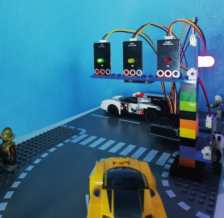
Fig. 1 exhibits our site visitors gentle assembled and positioned on a LEGO mannequin.
Properly, having stated that, we now have defined the electronics and we are able to now dedicate ourselves to the software program side, with the applying code proven in Itemizing 1: in it, we see that the site visitors gentle LEDs are managed by digital pins 11 (inexperienced) 12 (yellow) and 13 (pink), whereas digital pins 8 (blue) 9 (inexperienced) and 10 (pink) are assigned to drive the RGB LED. The contact sensor is learn by way of digital I/O 7, which has been initialised as an enter.
Itemizing 1
#outline ledAutoR 13 //pink LED module
#outline ledAutoG 12 //yellow LED module
#outline ledAutoV 11 //inexperienced LED module
#outline ledPedoniR 10 //RGB pink
#outline ledPedoniG 9 //RGB inexperienced
#outline ledPedoniB 8 //RGB blue linked simply to keep away from having a cable round
#outline contact 7 //sensor
//ready time
int intervallo=5000;
int worth; //variable for studying
void chiamata();
void setup() {
// definizione enter output
pinMode(ledAutoR, OUTPUT);
pinMode(ledAutoG, OUTPUT);
pinMode(ledAutoV, OUTPUT);
pinMode(ledPedoniR, OUTPUT);
pinMode(ledPedoniG, OUTPUT);
pinMode(ledPedoniB, OUTPUT);
pinMode(contact, INPUT);
}
void loop() {
worth=digitalRead(contact);
if(worth==HIGH){ //site visitors gentle name
chiamata();
}
//pink automotive led inexperienced pedestrian led
digitalWrite(ledAutoR, HIGH);
digitalWrite(ledAutoG, LOW);
digitalWrite(ledAutoV, LOW);
digitalWrite(ledPedoniR, LOW);
digitalWrite(ledPedoniG, HIGH);
digitalWrite(ledPedoniB, LOW);
delay(intervallo);
//Yellow LED Automotive Inexperienced LED Pedestrian
digitalWrite(ledAutoR, L
A GARAGE FOR SORTING SUPERCARS
We don’t essentially have to go away our supercar on the street, even whether it is manufactured from LEGO; for instance, we are able to retailer it in a comfortable storage. To make this storage extra reasonable, we are able to add some digital alerts to point to the mini-figures passing by within the mannequin if and which automotive is about to go away its storage, to be able to keep away from disagreeable accidents!
A type of energetic signposting that wouldn’t harm in actuality.
The fabric required for this train is as follows:
- LED module of your alternative;
- buzzer with or with out electronics;
- photo-resistance or ambient gentle sensor;
- Arduino One.
Initially, we now have to construct a storage appropriate for our supercar(s). As soon as that is performed, we are going to place the photoresistor contained in the storage. The photoresistor is a variable resistor that studies a bigger or smaller analogue worth relying on the quantity of sunshine perceived, whereas the ambient gentle sensor works in the identical means however is just not a variable resistor. The brighter the setting, the nearer the values are to zero; vice versa at the hours of darkness. The LED and the buzzer, then again, we are going to place exterior the storage.
As for the 2 gentle sensors, since they’re analogue sensors, their Sign pin must be linked to one of many analogue ports of the Arduino Uno, whereas the buzzer and the LED are each assigned to digital outputs. Since they each work on the idea of sunshine, it’s all the time finest to check what they sense when the storage is open and when the storage is closed to be able to discover an approximate threshold worth.
This may be performed utilizing the code beneath.
#outline fotoresistenza A0

int valueF;

void setup() {

  pinMode(fotoresistenza, INPUT);

  Serial.start(9600);

}

void loop(){

    valueF=analogRead(fotoresistenza);

    Serial.println(valueF);

}
The selection of the buzzer is subjective as a result of in the marketplace this part is present in varied variations, able to emitting sounds at totally different frequencies. However that’s not all, as a result of there are buzzers with and with out electronics: if we use a buzzer with electronics, we are able to additionally merely join it to the facility provide and it’ll begin to sound due to a part in it that triggers the oscillation, whereas if we use a buzzer with out electronics (which is a pure piezo pad) it have to be pushed with a one-way variable voltage, in any other case it won’t emit any sound. Within the case of use with Arduino, within the first case, digital output at excessive logic degree is ample, whereas within the second case it’s essential to drive the buzzer with a PWM digital pin of Arduino Uno and activate it from software program.
On this package there are each forms of buzzers: the one with electronics has a sticker on the highest, whereas the one with out electronics doesn’t.
As soon as we now have discovered the edge worth and determined which buzzer to make use of, we are able to consider the ultimate design. The LED and buzzer will stay off till the photoresistor detects a ample worth better than the indicated threshold worth.
The firmware to be written to grasp the applying is proven in Itemizing 2.
In it we see that the acoustic signalling is finished by digital pin 8, the switching on of the signalling LED that illuminates the street sign by pin 13 and the studying of the photoresistor is finished by analogue line A0, which on this case acts as an enter.
Within the loop, we now have the cyclical studying of the photoresistor standing and the resultant administration of the visible (LED) and acoustic (buzzer) signalling.
Itemizing 2
#outline buzzer 8
#outline led 13
#outline fotoresistenza A0
int sensorValue = 0;
int soglia=150; //photoresistance threshold
void setup() {
// put your setup code right here, to run as soon as:
Serial.start(9600);
pinMode( fotoresistenza, INPUT);
pinMode( led, OUTPUT);
pinMode( buzzer, OUTPUT);
}
void loop() {
// put your most important code right here, to run repeatedly:
sensorValue = analogRead(fotoresistenza);
Serial.println(sensorValue);
if(sensorValue>soglia){
digitalWrite(led, HIGH);
digitalWrite(buzzer, HIGH);
delay(100);
}
else{
digitalWrite(led,LOW);
noTone(buzzer);
}
}
SAFE DRAWER
We now transfer on to our third instructing software, which consists of constructing a “protected” drawer.
Run out of concepts about the place to cover valuables? There’s no purpose why you shouldn’t put them in a drawer manufactured from LEGO, even higher if it has a classy burglar alarm system.
So let’s see what we have to make this software; the fabric required is:
ambient gentle sensor or photoresistor;
- LED;
- buzzer;
- IR receiver;
- IR distant management;
- button;
- Arduino One;
- 3V CR2025 battery (not included within the package).
The operation of this “clever” drawer is, to say the least, easy however on the similar time suggestive: the ambient gentle sensor or the photoresist, positioned on the high of the drawer, will detect when the drawer is opened; however the system is designed in such a means that so as to not set off the alarm, it’s first crucial to pick out the proper key utilizing the distant management, to be able to authenticate oneself.
If the button is the fitting one, the “clever” drawer will recognise us because the proprietor, in any other case, the buzzer will sound and the LED will flash. On the similar time, a 16×2 show on the I²C-Bus interface will present both the message “welcome” or the message “to the thief” (Fig. 2) relying on whether or not the individual opening the drawer has authenticated himself or not.
The 16×2 LCD (Liquid Crystal Show) (16 columns and a couple of rows for writing) with I²C (Inter-Built-in Circuit, a protocol that enables alerts to journey in parallel) interface is an alphanumeric show to indicate on display screen writings, numbers or values that might usually be displayed on the Arduino serial monitor.
On this package, the show is already soldered to the I²C interface. It has 4 pins: GND, VCC(5V), SDA (information) and SCL (clock sign) to be linked respectively to the pins devoted to the I²C-Bus interface.
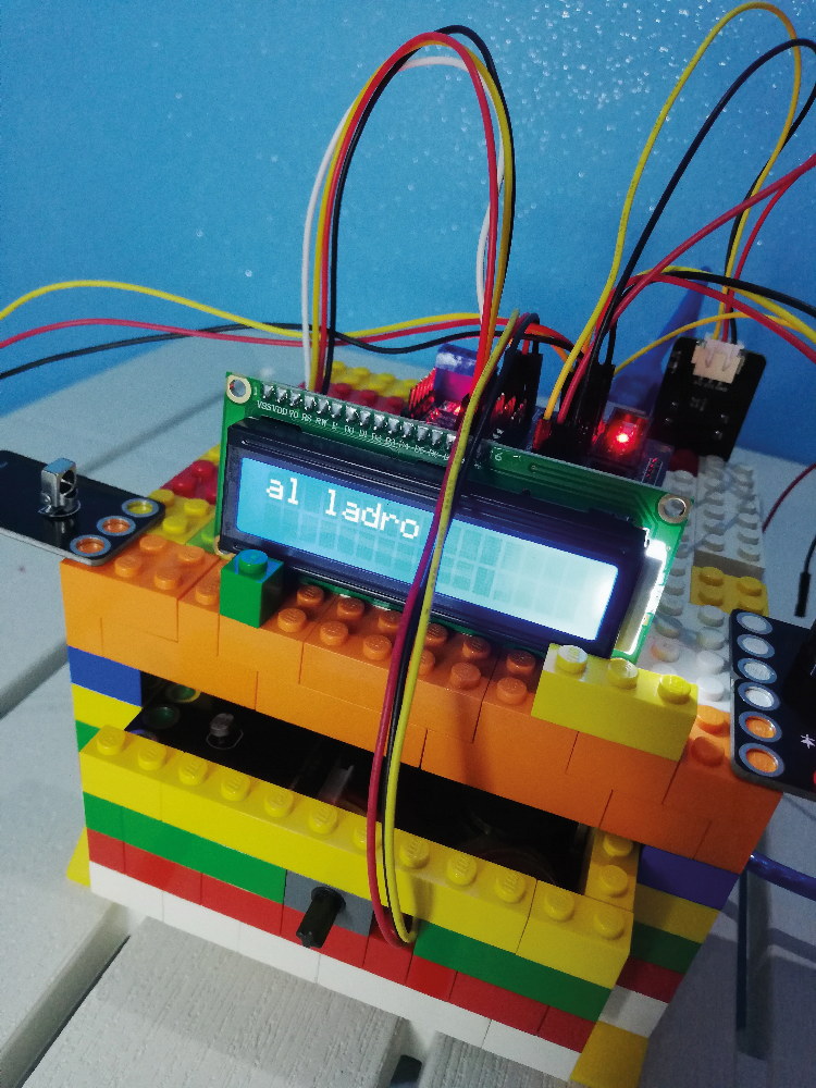
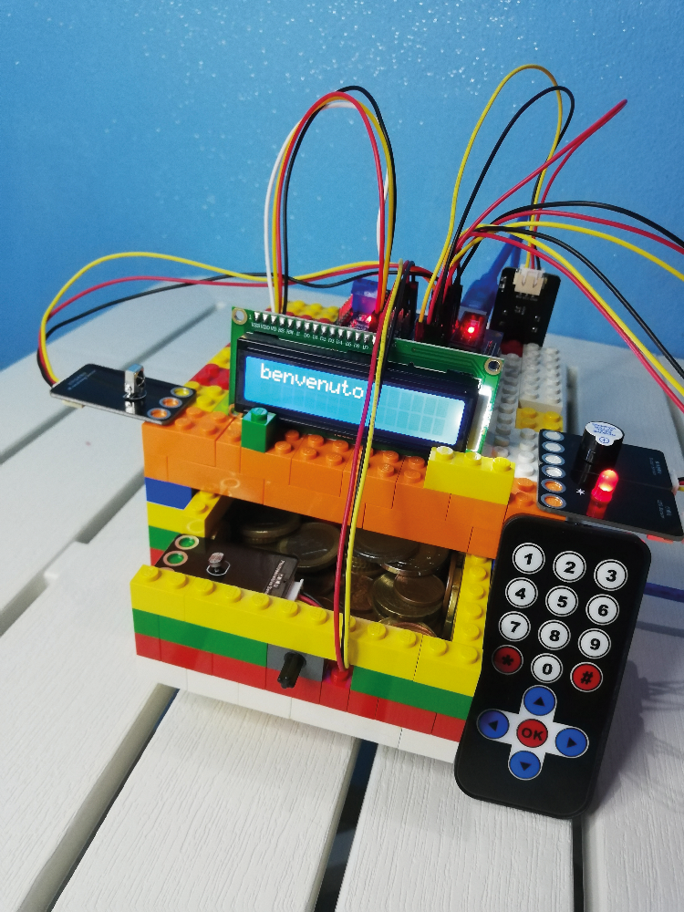
Fig. 2
Due to the SDA and SCL pins we are able to join as much as 4 shows in parallel, differentiating every system with a unique deal with.
On the entrance of the LEGO brick drawer is a backlit LCD show, and on the rear, on the I²C interface, is a trimmer from which the brightness of the show could be adjusted.
To grasp the way it works, check with the code in Itemizing 3.
Itemizing 3
//library required to make use of the show
#embody <LiquidCrystal_I2C.h>
//liquid crystal display is the title of the show on this sketch
//0x27 is the show deal with
//16 is the variety of columns (0-15)
//2 is the variety of rows (0-1)
LiquidCrystal_I2C liquid crystal display (0x27, 16, 2);
void setup() {
liquid crystal display.init(); //initialises the show
liquid crystal display.backlight(); //initialises the backlight
}
void loop() {
//to maneuver the show cursor
liquid crystal display.setCursor(colonna, riga);
//to jot down textual content I take advantage of ("")
liquid crystal display.print(“testo”);
//to jot down a variable I solely use the ()
liquid crystal display.print(variabile);
}
The distant management makes use of infrared expertise to speak with the IR receiver module. The receiver has 3 pins: GND, VCC (5V) and Sign (digital pin D11), whereas the distant management has 10 numeric keys, 4 arrows, hash mark, asterisk and okay. Infrared transmission is at a excessive frequency (roughly 38 kHz) from the distant management, which emits a sequence of bits (0 and 1) representing the assorted buttons; this sequence is intercepted by the receiver which, by way of this system, is aware of which button it corresponds to.
The button has the duty of constructing this system retailer the precise code, which is why it have to be positioned hidden.
Additionally, for this program (its code is proven in Itemizing 4) it’s higher to judge the precise threshold worth of the photoresistor (learn from analogue pin A0) contained within the gentle sensor. Within the code we see to begin with the inclusion of the library for the infrared sensor, which is learn from pin D11; the LED is as an alternative pushed by Arduino Uno’s D13 and the buzzer by D8. D3 is used to learn the button.
Within the loop, the button is managed with its studying, in addition to the replace of the LCD show for which the LiquidCrystal_I2C.h library was included at the start. The studying of the sunshine sensor to confirm the opening of the drawer and the prior reception of the code of the alarm launch button are additionally managed.
Itemizing 4
//library required for infrared management
#embody <IRremote.h>
//library required for displya
#embody <LiquidCrystal_I2C.h>
#outline IR_RX 11 //pin del ricevitore IR
#outline LED 13
#outline button 3 //settings button
#outline buzzer 8
#outline luce A0
int soglia=150; //threshold worth gentle
unsigned lengthy tasto; //variable with the important thing code
IRrecv irrecv(IR_RX); //declaration iR
decode_results outcomes; //conversion from bit to decimal
//liquid crystal display is the title of the show on this sketch
//0x27 is the show deal with
//16 is the variety of columns (0-15)
//2 is the variety of rows (0-1)
LiquidCrystal_I2C liquid crystal display (0x27, 16, 2);
void setup()
{
pinMode(luce, INPUT);
pinMode(LED, OUTPUT);
pinMode(button,INPUT);
pinMode(buzzer,OUTPUT);
irrecv.enableIRIn(); //IR activation
Serial.start(9600);
liquid crystal display.init(); //initialises the show
liquid crystal display.backlight(); //initialise backlighting
}
int on = 0;
unsigned lengthy final = millis();
void loop() {
Serial.println(tasto);
int buttonState = digitalRead(button);
delay(100);
if ( buttonState == HIGH) {
Serial.println(“Impostazioni...”);
if (irrecv.decode(&outcomes) && millis() - final > 250){
tasto = outcomes.worth;
Serial.println(“Memorizzo il nuovo codice”);
Serial.println(tasto); //secret's the variable the place the proper secret's saved
Serial.println(outcomes.worth);
final = millis();
irrecv.resume();
}
}
if (irrecv.decode(&outcomes)){
if ((millis() - final > 250 && outcomes.worth==tasto )&&(analogRead(luce)>soglia)) {
//to maneuver the show cursor
liquid crystal display.setCursor(0, 0);
//to jot down textual content I take advantage of ("")
liquid crystal display.print(“benvenuto”);
digitalWrite(buzzer, LOW);
}
else if ((millis() - final > 250 && outcomes.worth!=tasto )&&(analogRead(luce)>soglia)) {
digitalWrite(LED, HIGH);
digitalWrite(buzzer, HIGH);
liquid crystal display.clear();
liquid crystal display.setCursor(0, 0);
liquid crystal display.print(“al ladro”);
}
final = millis();
irrecv.resume();
}
}
THE INTELLIGENT VASE
And right here we’re on the final instructional software that we are going to suggest on this article and that considerations those that have a roughly “inexperienced” “thumb”. These days LEGO bricks are used to make something, so why not use them to construct a pot for a plant? Maybe with sensors utilized to inform us when the little plant inside is “thirsty” and wishes watering?
Properly, if you wish to do this and construct this ‘good’ pot, you might want to use the next parts:
- soil moisture sensor;
- liquid degree sensor;
- Pink and inexperienced LEDs;
- Arduino One.
Maybe we must always use Lego Duplos to make a vase, to make life a bit of simpler, however don’t fear about compatibility between the 2 ‘collection’ of bricks, as a result of the LEGO bricks match completely into the Duplos.
The intention of this experiment is to watch the well being of a plant utilizing two sensors.
The primary is the one which measures soil moisture by detecting the volumetric water content material, which is finished by detecting the dielectric fixed of the soil utilizing capacitive expertise. The measurement system makes use of a frequency of 70 MHz, which minimises interference on account of salinity. The second sensor detects the extent of water current, offering a corresponding voltage worth on an analogue pin; it gives zero volts if it isn’t involved with the water, however as it’s immersed the conductivity will increase and so do the output values.
The LEDs are used to point the present standing of the plant. For each sensors, nonetheless, threshold values have to be calculated, that are then imported into the ultimate program; the routine for calculating the humidity utilizing the liquid degree sensor is as follows:
#outline Lacqua A0

int valueL;

void setup() {

  pinMode(Lacqua, INPUT);

  Serial.start(9600);

}

void loop(){

    valueL=analogRead(Lacqua);

    Serial.println(valueL);

}
As an alternative, the one for calculating the edge worth for the dry land situation is:
#outline Hterra A0

int valueH;

void setup() {

  pinMode(Hterra, INPUT);

  Serial.start(9600);

void loop(){

    valueH=analogRead(Hterra);

    Serial.println(valueH);

}
As soon as the suitable measurements have been made, we are able to check the ultimate program, which corresponds to the code proven in Itemizing 5.
Itemizing 5
#outline Hterra A0
#outline Lacqua A1
#outline ledR 13
#outline ledV 12
int sogliaTerra = 150;
int sogliaAcqua = 150;
int valueH, valueL;
void setup() {
// put your setup code right here, to run as soon as:
pinMode(Hterra, INPUT);
pinMode(Lacqua, INPUT);
pinMode(ledR, OUTPUT);
pinMode(ledV, OUTPUT);
}
void loop() {
// put your most important code right here, to run repeatedly:
valueH = analogRead(Hterra);
valueL = analogRead(Lacqua);
if((valueH>sogliaTerra)||(valueL>sogliaAcqua)){
digitalWrite(ledR, HIGH);
digitalWrite(ledV, LOW);
}
else{
digitalWrite(ledR, LOW);
digitalWrite(ledV, HIGH);
}
}
CONCLUSIONS
On this article, we now have offered the ARDULEGOKIT, a set of digital parts in breakout board format designed to be utilized to LEGO bricks and for use in functions ruled by digital circuits managed by Arduino Uno via the interface supplied by a selected protect.
These are 4 software examples to be thought-about as workouts wherein we now have tried to indicate you how one can use as many circuit parts as attainable, additionally explaining how one can write firmware to implement the administration via the Arduino Uno board.
After all, on the idea of what has been defined, every of you’ll be able to develop functions as you see match.
Even earlier than the looks of instructional units such because the ARDULEGOKIT, it was tough, to say the least, to restrict your creativeness when utilizing LEGO bricks. Now, due to the probabilities of this package, whether or not you’re an knowledgeable or a newbie on this planet of electronics and programming, you’ll be able to lastly say goodbye to the boundaries of your creativeness and have enjoyable with LEGO and its developments.
FROM OPENSTORE